IPv4 header validation and rewrite on XISA™
Improving the trivial IPv4 switching program
This tutorial extends the Simple IPv4 program on the X-Switch ISA (XISA) with the validation and rewrite a real forwarding path needs. The Match-Action Processor validates the IPv4 version, header length, TTL and checksum, decrements the TTL, and updates the checksum before forwarding. To cut processing time, XISA runs the validation, destination lookup and rewrite in parallel.
Getting realistic: IPv4-header validation using X-Switch ISA
Welcome back network enthusiasts! We're Xsight-ed to continue our deep dive into the inner workings of programmable network switches using the X-Switch Instruction Set Architecture (XISA).
Our journey began with the fundamentals – exploring a basic cross-connect example to see how packet forwarding works at the microcode (uCode) level. We then took a significant step forward by tackling a Simple IPv4 switching program, which introduced concepts such as packet parsing to identify headers and fields, preloading data into MAP registers, and performing Longest Prefix Match (LPM) lookups incorporating VRF functionality.
While that basic IPv4 example was crucial for understanding core forwarding logic and table lookups, we deliberately streamlined it for clarity.
Today's example will show how to implement a more realistic program using XISA by adding the previously omitted, yet critical features normally present in any IPv4 switching program, namely IPv4 header validation and rewrite. You'll see how XISA provides the granular control required not just to inspect packets, but to verify their integrity through detailed validation checks and dynamically modify headers as needed.
To begin with, let's define the functionality that was missing from our previous Simple IPv4 switching example, but essential for a more complete implementation.
As a first step we'll add the IPv4 header validation to ensure that the IPv4 header is structurally and semantically correct – and therefore verify the following:
- IPv4 protocol version field is set to 4 (i.e. 4'b0100).
- IPv4 Internet Header Length (IHL) is no less than 5 (32-bit words); yes, this program supports IPv4 headers with options!
- IPv4 Time to Live (TTL) field is greater than 2.
- IPv4 header checksum is correct.
After completing the IPv4 header validation, we'll need to modify the IPv4 header by:
- Decrementing the TTL by 1.
- Updating the IPv4 header checksum.
Lastly, once these modifications are complete, the packet can be sent out to its destination port, just as we did in our previous Simple IPv4 example.
Beyond demonstrating the new XISA instructions used to perform all these operations, we'll also discuss how to parallelize them in order to make processing more efficient.
The basic plan
Overall, this example's program structure will be the same as in the previous example; here we'll concentrate mostly on the additions we described above.
Both IPv4 header validation and rewrite are performed in the Match-Action Pipeline (MAP). To support these operations, the MAP needs access to more IPv4 header fields than in our previous example, where only the Destination Address was loaded by the Parser for the destination lookup. As such, we'll amend the Parser code to extract and load the additional fields from the IPv4 header into the MAP registers.
The rest of the processing is done in the MAP. What's important, however, is to organize the processing to take advantage of the parallelism afforded us by XISA. In typical software implementations, these steps would be executed sequentially: first verifying the header, then performing the lookup and finally – assuming the packet is going to be sent out – modifying it. XISA can, however, run multiple instructions in parallel, allowing us to significantly reduce the time required to run the program as depicted in Figure 1.
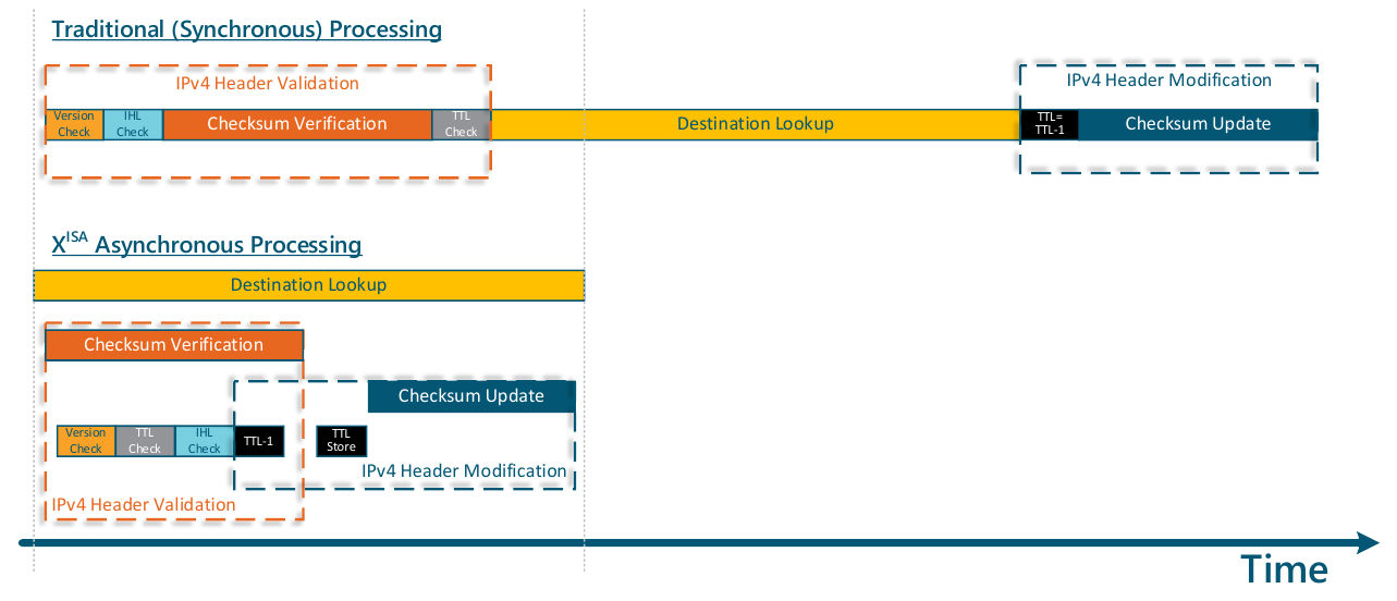
Figure 1. Synchronous vs. asynchronous processing
We'll continue to explore the microcode (uCode) in detail in the following sections. Also, see our recently opened XISA for further Instruction details.
Examining the microcode: a simplified XISA flow
XISA processes packet switching first via the Parser, and then via the MAP.
Parser uCode
Packet processing in the Parser has several goals.
Register planning
Since this new example requires us to examine other fields in the IPv4 header, it is a good idea to preload them into the MAP registers. In our previous example, we already preloaded the last word of the IPv4 Header (the 32-bit Destination IP address field) into R2.3. Since the fixed portion of an IPv4 header is 160 bits (five 32-bit words) wide, we'll need 4 additional 32-bit register words to load the fields.
Given the relative abundance of MAP registers, there's no need to optimize the code for the register space (yet); we can simply load the first 4 words (128 bits) of the IPv4 header into another MAP register (R4).
As shown in Figure 2 we decided to leave the IPv4 Destination Address in the same location as in our previous example (R2.3) (fewer changes to our code!) and use another spare register (R4) to store the first 16 bytes of the IPv4 header.
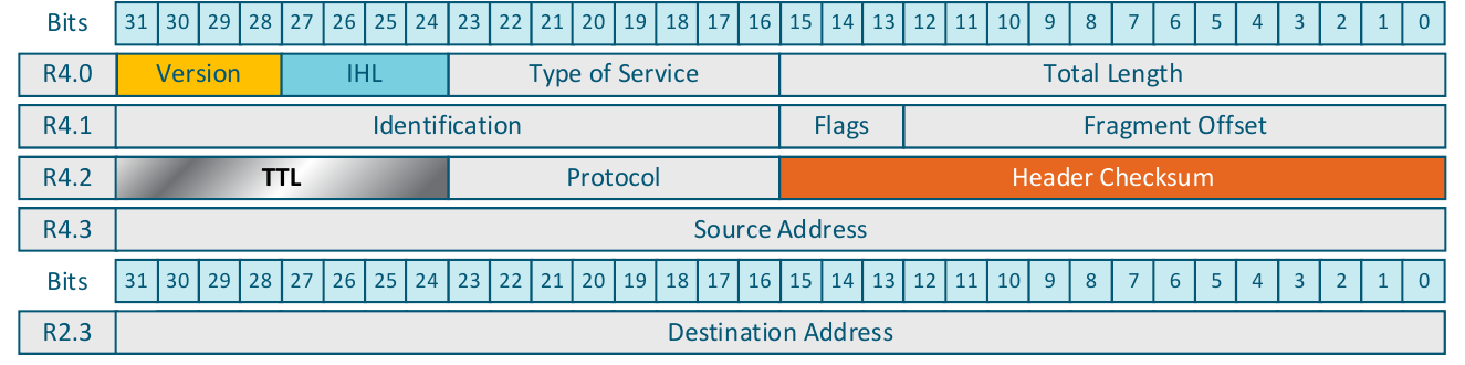
Figure 2. Preloading the IPv4 header into MAP registers
Writing the Parser code
The only change we need to make to the previous Parser code is in the state entry_point_ipv4 where we will execute one extra instruction to preload the first 128 bits of the IPv4 header into MAP register R4.
Figure 3. Parser code (fragment)
entry_point_ipv4: EXTMAP MAPR4, 0, 0, 128 # Load the bytes 0-15 of the IPv4 header EXTMAP MAPR3, 0, 128, 32 # Load the IPv4 address STHC.H 20, 1, 1, 0- Line 21: EXTMAP MAPR4, 0, 0, 128: We're already familiar with the EXTMAP (EXTract to a MAP register) instruction from our previous example. It loads the data from the packet buffer into the MAP register, so that it can be accessed by the Match-Action Processor. This additional instruction loads the first 16 bytes (128 bits) of the IPv4 header into MAP register R4 (see Figure 2).
And that's all we need to do. As a reminder, the MAP retains full access to the packet headers even if they are not loaded into the MAP registers. Thus, the Parser programmer can choose whether (or not) to load header fields, based on program requirements, register space availability and other factors.
MAP code
Now, let's look at the MAP microcode needed to implement the algorithm, graphically depicted in Figure 1. We will not be discussing the details of the actual forwarding decision, since they are going to be exactly same (we even preserved the register layout), and concentrate on IPv4 header validation and modification instead.
Validating individual IPv4 header fields
XISA provides a rich set of instructions that can perform comparisons and conditional jumps. Let's see how we can utilize them to validate the IPv4 version, IPv4 IHL and the TTL fields.
Figure 4. IPv4 version, IPv4 header length and TTL validation
v1 CMPI R4.0, 28, 4, 4v2 BRINEQ ipv4_version_invalidv3 CMPI R4.0, 24, 5, 4v4 BRILT ipv4_ihl_invalidv5 CMPI R4.2, 24, 2, 8v6 BRILT ipv4_ttl_too_small- Line v1: CMPI R4.0, 28, 4, 4: The CMPI (CoMPare Immediate) instruction compares the contents of an arbitrary bit field to an immediate operand. The bit field is expressed using the three operands that represent the register (the first operand), the bit offset of the field (the second operand) and the bit size of the field (the fourth operand of the instruction). In our case the instruction compares the 4-bit-wide IPv4.version field, located in register R4.0 (at offset 28), see Figure 2, with an immediate value of 4 (third operand).
- Line v2: BRINEQ ipv4_version_invalid: The comparison instructions (including CMPI) set the so-called condition codes that can be examined and acted upon by a set of conditional branch instructions. In this case, the BRINEQ (BRanch Immediate if Not EQual) jumps to the label ipv4_version_invalid (defined later) if the value of IPv4.version field is not equal to 4.
- Lines v3–v4: As in lines v1–v2, these lines are used to compare the contents of the 4-bit field located at offset 24 in register R4.0 with the immediate value of 5. Figure 2 indicates that this is the IPv4.ihl field. The subsequent BRILT (BRanch Immediate if Less Than) jumps to the label ipv4_ihl_invalid when the IPv4 header length is less than five 32-bit words (20 bytes), which is the minimal value allowed for IPv4 IHL.
- Lines v5–v6: These lines ensure that the value of IPv4 TTL is not less than 2, since IPv4 packets with TTL equal to 0 or 1 should be dropped and not forwarded. See Figure 2 for the exact location of the IPv4 TTL field.
Validating the IPv4 header checksum
IPv4 checksum validation is a mandatory requirement for any IPv4 switch or router; packets with an incorrect IPv4 header checksums must not be forwarded.
To verify the IPv4 checksum (as per RFC791) one needs to split the entire IPv4 header into 16-bit words (there will be IHL*2 of them) and calculate their sum using ones' complement addition. If the value of that sum is equal to zero (using ones' complement system, that is 0000₁₆ or FFFF₁₆) then the checksum is correct.
XISA provides much flexibility in terms of where and how to compute and validate the IPv4 checksum.
First, both the Parser and the MAP contain the relevant instructions. Thus, the data plane programmer has the option to decide where to perform the header checksum validation.
Secondly, the MAP contains both a universal CHKSUMCALC instruction that can compute ones' complement sum using the algorithm described in RFC1141, and a specialized instruction CHKSUMTST that is aware of the IPv4 header format and thus greatly simplifies the IPv4 checksum verification.
Figure 5 shows how the specialized instruction works. It uses the Header Offset ID (Layer ID) that corresponds to the IPv4 header to find its location in the packet buffer [1]. From there, the instruction retrieves the IPv4.ihl field that specifies the length of the IPv4 header (including IPv4 options) in terms of 32-bit words [2]. That is all the information that is required to verify the IPv4 header checksum: the hardware can then logically split these words into 16-bit chunks and add them all together [3], using the one's complement addition and check the result.
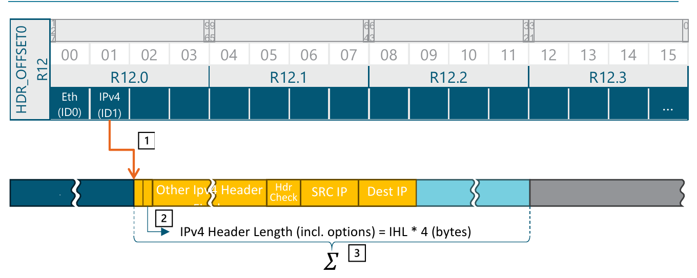
Figure 5. Specialized instructions for IPv4 checksum update and verification
Given that the IPv4 checksum computation might involve accessing up to 60 bytes, the instruction is designed to run asynchronously as in the usage example in Figure 6.
Figure 6. IPv4 header checksum verification
c1 CHKSUMTST.LF1 1c2 SYNC.N 2, bad_ipv4_checksum- Line c1: CHKSUMTST.LF1 1: The CHKSUMTST (CHecK SUM TeST) instruction takes a single parameter – the Offset ID (Layer ID) of the IPv4 header. As you may recall from the Simple IPv4 example (see Table 1), the IPv4 Header is assigned an offset ID of 1. Since the instruction runs asynchronously, we'll allocate the LF1 completion flag to synchronize the execution (wait for the instruction completion).
- Line c2: SYNC.N 2, bad_ipv4_checksum: This instruction waits for the CHKSUMTST instruction to complete. Since we used the LF1 flag, the bitmask of flags to wait on should have bit number 1 set, which results in a value of 2. The .N (No match) suffix specifies that if there is no match (i.e. the calculated checksum value didn't match the one present in the packet), the code should jump to the label specified as the second operand, bad_ipv4_checksum.
Decrementing the TTL
Decrementing the TTL is a two-step operation. Recall that the TTL value was already loaded in register R4.2. Thus, the first step would be to use the subtract instruction to decrement it. However, this is not going to change the value in the packet buffer! Therefore, we need to explicitly store the decremented TTL in the packet buffer, using another specialized instruction.
Figure 7. Decrementing TTL and updating the packet buffer
t1 SUBI R0.0, R4.2, 24, 8, 1t2 STH.SYNC R0.0, 1, 8, 1- Line t1: SUBI R0.0, R4.2, 24, 8, 1: The SUBI (SUBtract Immediate) instruction subtracts its last immediate operand (1) from the field, specified by the preceding three operands. The TTL is an 8-bit field located in register R4.2 at offset 24. The result of the subtraction can be placed into any 32-bit register, so we'll choose R0.0 for that purpose. It's important to note that the result is always placed into the least significant bits of the register.
- Line t2: STH.SYNC R0.0, 1, 8, 1: The STH (STore in the Header) instruction copies 1 to 16 bytes stored from the specified register (R0.0 in our case) into the packet buffer. The specific location is specified as the Header Offset ID (the second operand, 1; see Table 1 from Simple IPv4 example) and the offset inside that header in bytes (the third operand, 8). The TTL field is located at the 8th byte offset from the beginning of the IPv4 header. The last operand specifies the number of bytes to store (1). The option suffix .SYNC synchronizes the instruction flow with the store operation by ensuring that the sole operation completes before the next instruction is executed.
Updating the IPv4 checksum
To update the IPv4 checksum we'll use another specialized MAP instruction (CHKSUMUPD) that works in a manner similar to the previously discussed CHKSUMTST instruction.
Figure 8 shows how this specialized instruction works. It uses the Header Offset ID (layer ID) that corresponds to the IPv4 header to find its location in the packet buffer [1]. From there, the instruction retrieves the IPv4.ihl field that specifies the length of the IPv4 header (including IPv4 options) in terms of 32-bit words [2]. That is all the information that is required to verify IPv4 header checksum: the hardware can then logically split these words into 16-bit chunks and add them all together [3], except for the 16-bit chunk that represents the hdr_chksum field [4], using the one's complement addition and check the result. The final result is inverted and written into the hdr_chksum field [4], since its location within IPv4 header is known.
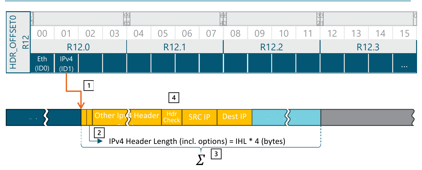
Figure 8. IPv4 checksum update instruction
Given that the IPv4 checksum computation might involve accessing up to 60 bytes, the instruction is designed to run asynchronously, as in the usage example in Figure 9.
Figure 9. IPv4 header checksum update
u1 CHKSUMUPD.LF1 1u2 SYNC 2- Line u1: CHKSUMUPD.LF1 1: The CHKSUMUPD (CHecK SUM UPDate) instruction takes a single parameter and that is the offset ID (Layer ID) of the IPv4 header. As before (see Simple IPv4 example, Table 1), a Header Offset ID of 1 is assigned to the IPv4 header. Since the instruction runs asynchronously, we allocate a completion flag, LF1, to synchronize the execution (wait for the instruction completion).
- Line u2: SYNC 2: This instruction waits for the CHKSUMUPD to complete.
Integrating the changes
Let's review the code that was written for the Simple IPv4 example:
The Simple IPv4 MAP code, annotated for reference
ingress: BRBTSTCLR R11.3, 1, not_ipv4_packet # IPv4 header present? CONCAT.CD R2.2, 0, R1.3, 0, 12 # Form the LPM key LKPLPM.LF5.R R0.3, R0.3, -1, -1, R2, R2, 0, 4 # Start LPM lookup SYNC.N 32, ipv4_lpm_miss # Wait for completion AQMEG.LF3.NOMIRR R0.0, R0.3 # Query the AQM MOVI R0.2, 0 # Prepare SENDOUT param MOVI.CD R3.3, 0 # Prepare advanced params SYNC 8 # Wait for AQMEG completion BRBTSTSET R0.0, 0, aqm_drop # Check AQM query result SENDOUT.H R0, R3, 0 # Send the packet and haltnot_ipv4_packet: # Error handling (drop and halt)ipv4_lpm_miss:aqm_drop: DROP.H 0host_eth: # Special packet paths (drop and halt)host_pss:exception:loopback:parser_congestion:trap: DROP.H 0It should be straightforward to determine where to insert the code for what we've just written. Probably inserting the code for the IPv4 header field and header checksum verification, before the LPM lookup, right after line 1; the TTL decrement and IPv4 checksum update code might typically be inserted after the LPM lookup, somewhere after line 5. Writing the code in this manner, however, will result in a sequential execution, as depicted in the top half of Figure 1.
Let's try and improve on this by utilizing the asynchronous execution of the XISA instructions.
Parallelizing the code
The bottom part of Figure 1 offers a graphical visualization of the plan that will aid us in modifying the assembly code. In addition, we'll use the same line numbers for the new code as we used in the previous figures. This structure allows the X-Switch to execute up to 3 operations in parallel, significantly reducing packet processing time.
Parallelized MAP code
1 ingress: 2 BRBTSTCLR R11.3, 14, not_ipv4_packet 3 CONCAT.CD R2.2, 0, R1.3, 0, 16 4 LKPLPM.LF5.R R1.3, R1.3, -1, -1, R2, R2, 0, 4c1 CHKSUMTST.LF1 3h1 CMPI R4.0, 28, 4, 4h2 BRINEQ ipv4_version_invalidh3 CMPI R4.0, 24, 5, 4h4 BRILT ipv4_ihl_invalidh5 CMPI R4.2, 24, 2, 8h6 BRILT ipv4_ttl_too_smallt1 SUBI R0.0, R4.2, 24, 8, 1c2 SYNC.N 2, bad_ipv4_checksumt2 STH.SYNC R0.0, 3, 8, 1u1 CHKSUMUPD.LF1 3u2 SYNC 2 5 SYNC.N 32, ipv4_lpm_miss 6 AQMEG.LF3.NOMIRR R1.0, R1.3 7 MOVI R1.2, 0 8 MOVI.CD R0.3, 0 9 SYNC 810 BRBTSTSET R1.0, 0, aqm_drop11 SENDOUT.H R1, R0, 01213 not_ipv4_packet: ipv4_version_invalid: ipv4_ihl_invalid: ipv4_ttl_too_small: bad_ipv4_checksum:14 ipv4_lpm_miss:15 aqm_drop:16 DROP.H 0The line labels in the left column show how the work overlaps. The LPM lookup started on line 4 runs on flag LF5 for the whole span down to line 5, and beneath it three groups proceed in parallel: c1–c2 validate the IPv4 checksum, h1–h6 validate the header fields, and t1–t2 decrement the TTL and store it back (T = TTL-1, then TTL = T). Once the checksum has been verified, u1–u2 update it. Figure 1 shows the same overlap on a timeline.
The figure below shows the same listing as it appears in the specification, with the brackets marking each group of concurrent operations.
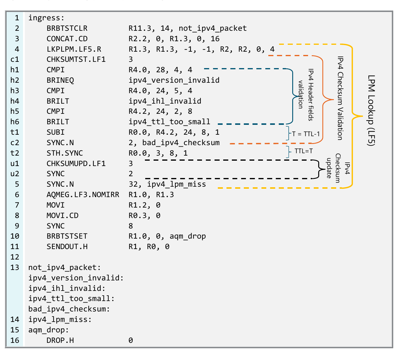
The parallelized MAP code, showing how the concurrent operations group
Beyond the simplicity: XISA's potential
This example demonstrates several new features and capabilities of the XISA architecture. We learned how to perform arithmetic operations and comparisons, how to use specialized accelerators for IPv4 checksum validation and rewrite, and how to access and modify the packet buffer directly from the code running on MAP. Even more importantly we saw how to parallelize execution of multiple instructions on XISA and significantly reduce execution time.
XISA is capable of handling much more sophisticated networking tasks. Any standard routing and/or bridging feature, and more importantly, any other unique or customer-driven feature can be implemented thanks to the X-Switch's extreme flexibility and programmability. For more information, contact us.
We, at Xsight Labs, believe this transparency will drive innovation and facilitate the development of future networking technologies.
Stay tuned for further insights into the capabilities of the X-Switch ISA and the exciting possibilities it unlocks.
Continue with the XISA tutorials
Previously: simple IPv4 forwarding. Next: per-port counters, so that no packet is dropped without leaving a trace.
XISA (the X-Switch Instruction Set Architecture) is Xsight Labs' open instruction set for programming packet processing on the X-Switch family, published under the Mozilla Public License version 2. Programs run across two stages: a Programmable Parser that identifies packet headers, and a Match-Action Processor (MAP) that performs lookups, edits and forwarding.